Validating vSTAR Accuracy and Your Own Logging Tool

News, Publications

Accuracy Claims Need a Ground Truth

Accuracy is fundamental to structural geology. A measurement may appear precise, but the real question is whether it reproduces the true orientation of the structure being measured. Comparing results between operators, devices, or manual methods can demonstrate agreement, but it does not necessarily establish which measurement is correct.

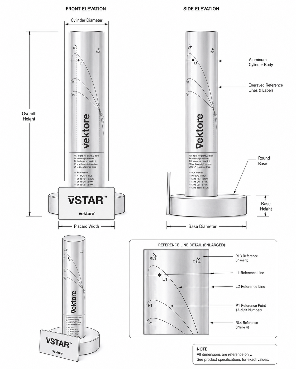
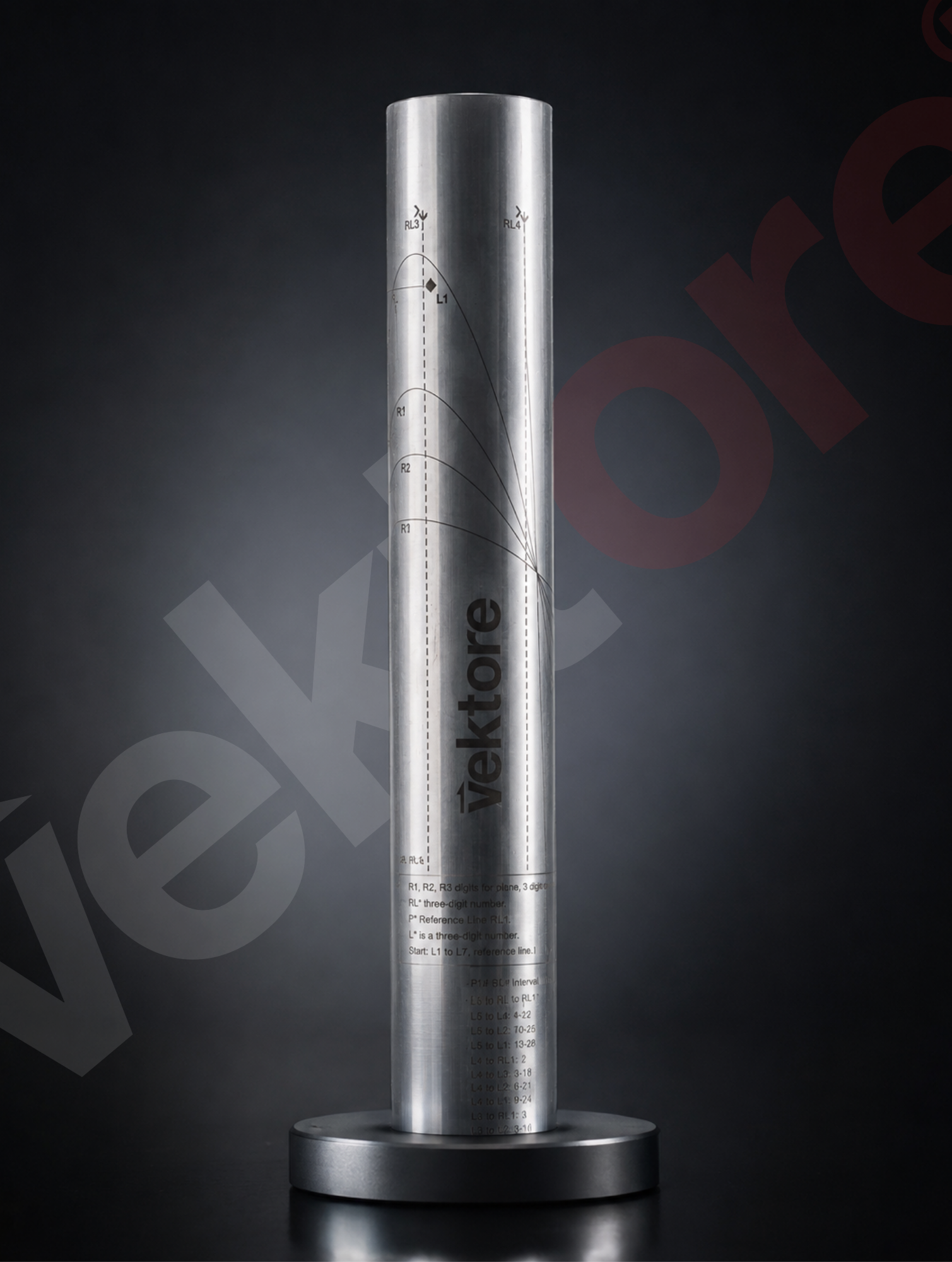
To validate vSTAR against a known reference, Vektore used a precision-machined aluminum cylinder with laser-etched geometric references. More than 100 structural measurements were collected and compared directly with their expected orientations, providing a controlled ground-truth test in which the reference geometry was known before each measurement was taken.

Why Use a Precision-Machined Validation Cylinder?

Natural drill core is not ideal for controlled accuracy testing because irregular surfaces, broken or cut core, orientation uncertainty, geological complexity, and operator interpretation can introduce additional variables.

The vSTAR validation prototype uses a precision-machined aluminum cylinder with laser-etched reference points, lines, and structural traces whose positions are precisely known. This provides a controlled physical ground truth, allowing the expected orientations to be determined independently of vSTAR and compared directly with the measured results.

The method does not depend on a specific cylinder size. What matters is that the validation object is manufactured accurately and contains known, independently verifiable geometry, making the approach reproducible for other structural logging systems as well. The complete cylinder diagram, including its reference points and structural traces, is available for review and reproduction: [Download the Cylinder Reference Diagram (SVG) →]

null

Dimensions

Cylinder length xx mm
Cylinder outside diameter xx mm
Radius xx mm
Material: Aluminum
Reference marking method: Laser etching
Number of reference planes:
Number of reference lineations:

Why Laser-Etched Reference Marks?

The reference geometry must remain stable throughout repeated testing. Unlike temporary or manually drawn marks, laser-etched reference points, lines, and structural traces are permanently fixed to the cylinder, reducing positioning uncertainty and allowing the same features to be measured repeatedly.

Most importantly, the reference geometry is defined independently of the logging tool being tested. The expected orientation is established before measurement, ensuring that the cylinder provides a true ground-truth reference.

Recommended Fabrication Method

To create a similar validation object, the reference geometry can first be designed in CAD relative to the cylinder’s known dimensions and axis. The geometry can then be transferred to the cylinder using a rotary laser-engraving system, including a longitudinal reference line to establish a common coordinate system for all features.

After fabrication, the cylinder and engraved reference positions should be dimensionally verified to ensure that the physical object accurately represents the designed geometry.

Accuracy, Precision, and Repeatability

Accuracy, precision, and repeatability describe different aspects of measurement quality. A tool may produce highly consistent results but still be inaccurate if those measurements are systematically offset from the true orientation. Similarly, agreement between operators demonstrates repeatability, but does not by itself establish ground-truth accuracy.

A robust validation should therefore determine whether the tool reproduces a known orientation, does so consistently, and maintains that performance across repeated measurements. This is why accuracy claims should be supported by a clearly defined ground truth, sufficient measurements, a transparent error calculation method, and clearly identified statistics such as median, percentile, or maximum error.

The vSTAR validation cylinder provides a controlled reference for making these measurements quantifiable, reproducible, and auditable.

Test Methodology

The objective was straightforward: measure how closely vSTAR could reproduce known structural orientations.

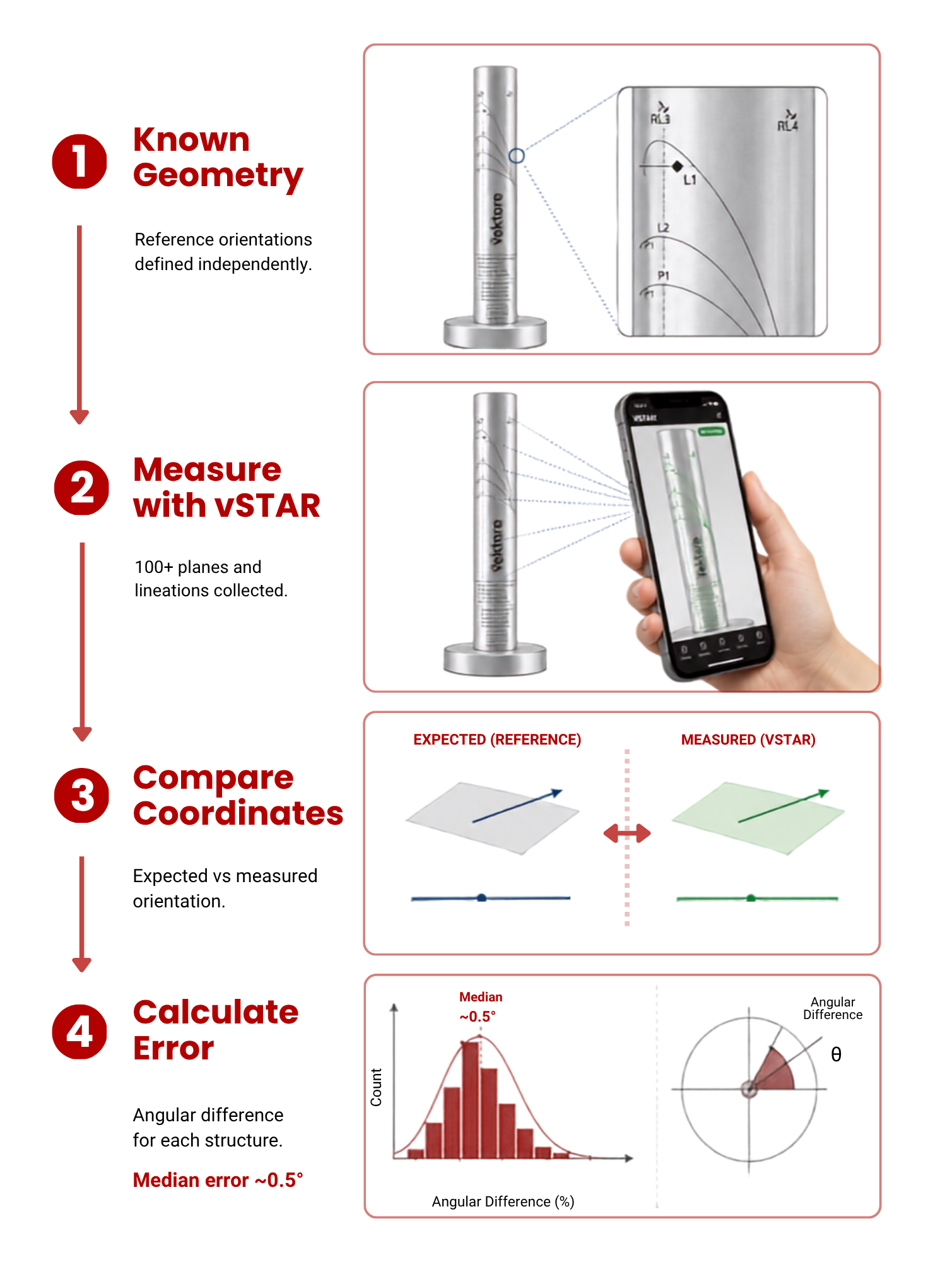
Planes and lineations were collected from the validation cylinder using the standard vSTAR logging workflow. Each measurement was compared with the expected orientation derived from the cylinder’s known geometry:

Known orientation → vSTAR measurement → angular difference

The angular difference between the expected and measured orientation represents the measurement error. For planes, this comparison uses the plane orientation; for lineations, it compares the corresponding linear orientations. This provides a three-dimensional measure of the actual orientation difference rather than comparing individual orientation parameters separately.

This three-dimensional angular difference was calculated for each measurement to evaluate the overall performance of the system.

Results: Median Error of Approximately 0.5°

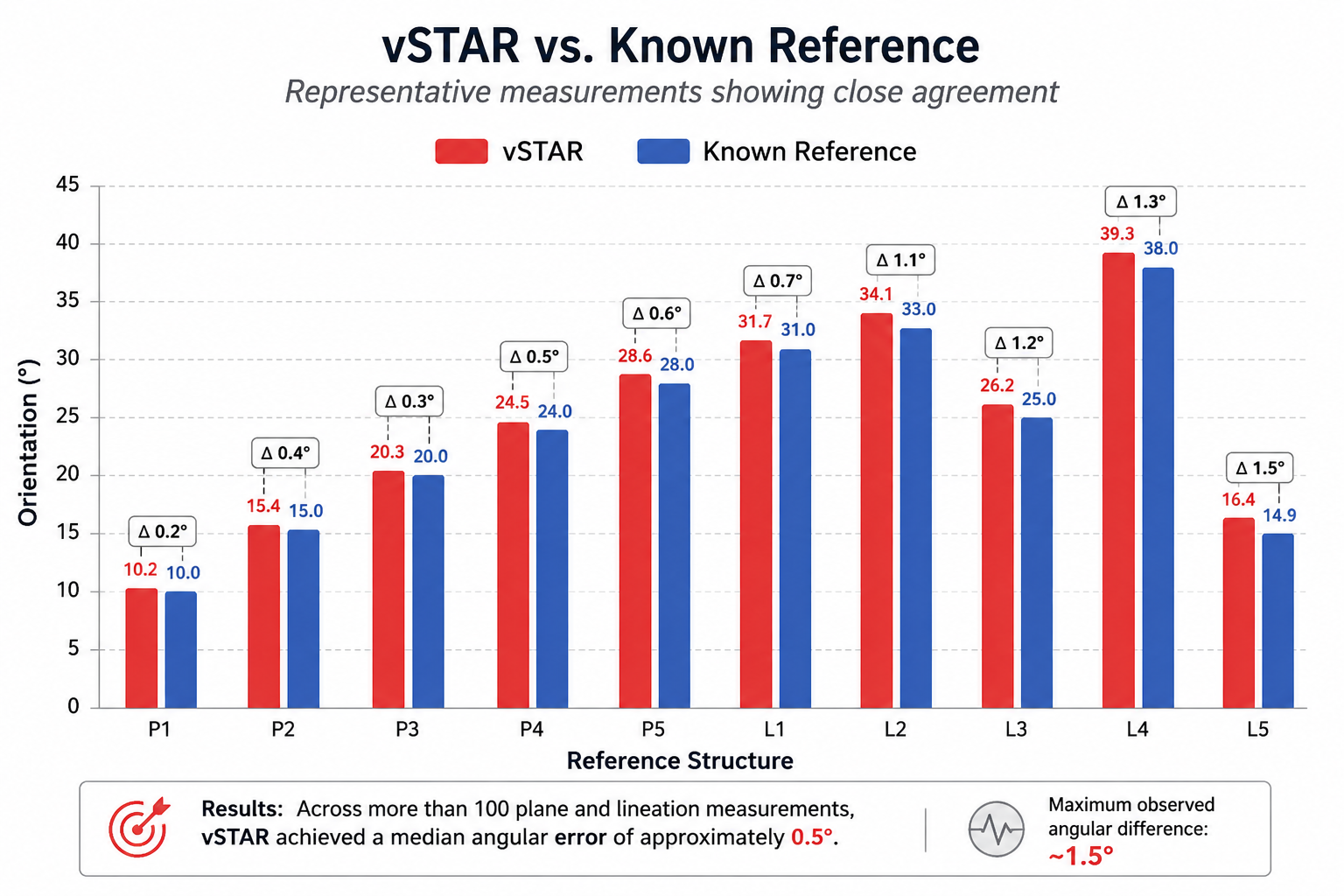
Across more than 100 plane and lineation measurements, vSTAR achieved a median angular error of approximately 0.5° when compared with the known reference geometry.

The median represents the middle of the error distribution, meaning approximately half of the measurements had an error below 0.5° and half above it. It provides a useful measure of typical performance because it is less affected by occasional higher-error measurements.

The observed errors were generally small, with higher-error measurements around 1.5°. Together, these results demonstrate how closely vSTAR reproduced the known structural orientations under controlled test conditions.

What Supports vSTAR AR Measurement Accuracy?

vSTAR uses fiducial markers to establish a stable visual reference frame for AR measurements. These markers have known identities, dimensions, and positions, allowing computer-vision algorithms to estimate the relative position and orientation between the camera and the reference system.

The Trilo combines multiple fiducial markers to provide redundancy. If some markers are partially obscured or outside the camera view, other visible markers can continue supporting the tracking solution. This allows vSTAR to maintain a consistent physical reference while operating on supported standard Android devices without requiring specialized tracking hardware.

Fiducial markers are widely established in computer vision, robotics, and augmented reality, but they are not themselves proof of vSTAR’s measurement accuracy. They provide the technological framework for AR tracking; the precision-machined validation cylinder provides the independent ground truth used to measure the system’s actual accuracy.


What the vSTAR Validation Demonstrates

Under controlled test conditions, vSTAR reproduced the known structural geometry of the validation cylinder with a median angular error of approximately 0.5°, establishing a measurable baseline for the system’s accuracy. Real-world results may vary due to factors such as core condition, visibility, operator selection, orientation quality, calibration, and acquisition geometry.

Ultimately, the reliability of structural datasets begins with the reliability of the measurements used to build them. The important question is not simply “How precise does the measurement look?”, but “How do we know the measurement is correct?” Ground-truth validation provides a practical way to answer that question for vSTAR and any structural logging technology that can be tested against known geometry.

Resources & References

To support reproducible testing, the following resources are available for download.

Cylinder Files

Cylinder Diagram — SVG
Technical drawing and reference geometry for manufacturing the validation cylinder.
[Download SVG →]

Validation Data

Reference Geometry Table
Ground-truth orientations for the planes and lineations used in the validation test.
[Download Reference Table →]

Accuracy Calculation Template
Spreadsheet for comparing measured and expected orientations and calculating angular error.
[Download Calculation Template →]

These files allow organizations to reproduce the validation approach and independently evaluate the accuracy of their structural logging workflow.

Leave a Reply

Your email address will not be published. Required fields are marked *

Fill out this field
Fill out this field
Please enter a valid email address.
You need to agree with the terms to proceed

Leave a Reply

Your email address will not be published. Required fields are marked *

Fill out this field
Fill out this field
Please enter a valid email address.
You need to agree with the terms to proceed

keyboard_arrow_up